

Radio frequency signals permeate our environment, carrying phone calls, guiding fighter jets, and...
Summary
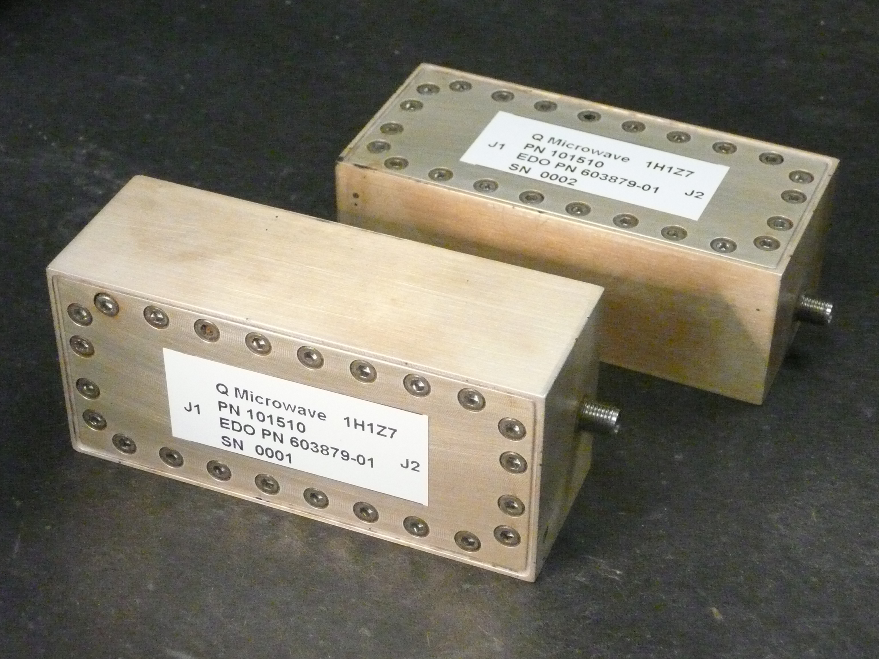
- Microwave components are essential elements of high frequency systems that shape electromagnetic wave behavior through their physical structure and material properties.
- Designing these systems requires careful trade-offs between signal integrity and hardware constraints to meet stringent performance targets.
- To achieve an effective system design, each component must operate in harmony with adjacent components to preserve signal quality and system stability from signal acquisition to final output processing.
A microwave component is a physical device designed to transmit, control, or process electromagnetic signals, typically ranging from 300 MHz to 300 GHz. Because these waves are so short, the materials and mechanical tolerances used in these components must be incredibly precise to maintain signal integrity.
This guide explores the different categories of microwave hardware and the critical trade-offs you must manage during the design process by answering the following questions:
- What exactly is a microwave component?
- What is the difference between active and passive microwave components?
- What is the difference between microwave components and lower frequency RF components?
- How do different types of microwave components function and interact in a system?
- What common trade-off should you consider when selecting or combining microwave components?
- How do you decide which microwave component to prioritize when designing a system?
- How can you evaluate and choose the right microwave component manufacturer?
What is a Microwave Component?
As explained above, a microwave component is a physical device specifically designed to transmit, control, or manipulate electromagnetic signals at microwave frequencies. These frequencies generally range from 300 MHz to 300 GHz, which are wavelengths ranging from 1 meter down to 1 millimeter.
Categories of Microwave Components
Microwave components are broadly classified into two categories, active and passive components.
Active Components
Active components require an external DC power source to operate. They control signal behavior through amplification, switching, or frequency conversion, and can introduce energy/provide gain within the RF signal path.
| Active Microwave Component | Function |
| Microwave transistor | Amplifies RF signals and provides gain in receiver and transmitter stages |
| Microwave integrated circuit (MMIC) | Combines multiple active functions such as gain, mixing, and switching on a single chip |
| Low-noise amplifier | Boosts weak incoming signals while minimizing added noise |
| Power amplifier | increases signal power for transmission to antennas or loads |
| Mixer | Combines two signals to shift frequency up or down for conversion stages |
| Oscillator | Generates a stable RF signal at a defined frequency |
| Frequency multiplier | Produces higher frequiencies from a lower frequency input signal |
| RF switch | Routes RF signals between different signal paths under control |
| Phase shifter | Adjusts the phase of an RF signal for beam steering or signal control |
Passive Components
Unlike active components, passive microwave components do not amplify signals. Instead, they guide, split, attenuate, reflect, or filter electromagnetic energy using their physical structure and material properties, without introducing additional power into the signal path.
What is the Difference Between Microwave Components and Lower Frequency RF Components?
Designing for lower RF frequencies such as AM, FM, and standard VHF or UHF systems differs from microwave frequencies above roughly 1 GHz due to a basic physical relationship, wavelength.
As frequency increases, wavelength decreases according to f = λ / c. Where:
- f is the signal frequency in hertz, which tells you how many cycles the wave completes each second.
- c is the speed of light in free space, which remains constant for electromagnetic waves in air.
- λ is the wavelength, which describes the physical distance covered by one full cycle of the wave.
At lower RF ranges, wavelengths are large compared to typical circuit dimensions, so components behave close to ideal lumped elements. However, at microwave frequencies above roughly 1 GHz, wavelengths shrink to a scale comporable to interconnects and component sizes, which causes signal behavior to become more distributed.
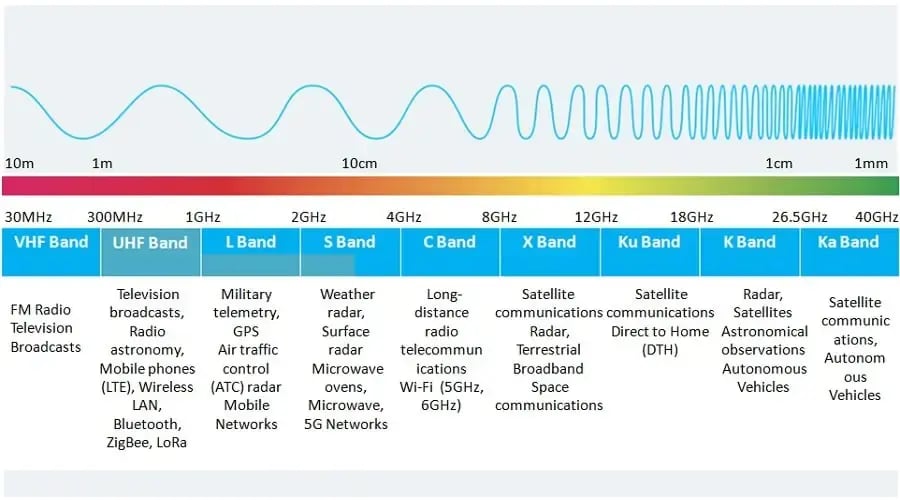
Microwave Frequency Bands via RF Page
How Do Different Types of Microwave Components Function and Interact in a System?
Microwave components work as connected building blocks in an RF system, where each stage modifies the electromagnetic signal as it moves through the circuit.
You can interpret their interaction more clearly when you treat the circuit as part of the signal chain. Let's take a closer look at this example.
.webp?width=1086&height=481&name=Single-Conversion-Superheterodyne-Receiver-Architecture%20(1).webp)
Functional Block Diagram of a Single-Conversion Superheterodyne Receiver Architecture.
- Signal Capture and Transition. The process begins at the antenna, where incoming electromagnetic waves are converted into guided electrical signals.
- Pre-Selection and Conditioning. The signal passes through a Bandpass Filter to establish the receiver's initial selectivity. This stage is critical for suppressing out-of-band blockers and helps contribute to image rejection before the signal enters the non-linear stages of the chain.
- Initial Amplification. The filtered RF signal is then amplified by the LNA. In this stage, your primary objective is to provide sufficient gain to overcome the noise figure of subsequent stages (per Friis' Formula) while adding minimal thermal noise to the link budget.
- Frequency Translation. The Mixer performs a non-linear multiplication of the RF signal and the Local Oscillator (LO) signal. This shifts the RF carrier to a fixed Intermediate Frequency (IF) based on the heterodyne principle fIF=| fRF ± fLO|.
- IF Filtering and Channel Selection. The IF filter provides sharp selectivity in the receiver. Since it operates at a lower fixed frequency, it can achieve a much higher Q-factor than the initial RF bandpass filter, allowing it to more effectively separate the desired channel from adjacent channel interference.
- IF Gain Stage. The IF Amplifier compensates for the conversion loss of the mixer and the insertion loss of the IF filter. It typically provides the bulk of the system's gain and often incorporates Automatic Gain Control (AGC) to maintain a constant signal level for the detector.
-
Demodulation and Baseband Recovery. Finally, the Demodulator extracts the original information (data out) from the IF carrier. Depending on the modulation scheme (e.g., QAM, PSK, or FSK), this stage handles the phase and amplitude recovery to produce the digital bitstream or analog output.
Throughout this journey, the stages cannot operate as isolated blocks. You must carefully balance the gain distribution across the chain to maintain sensitivity without compromising dynamic range. For instance, if your LNA applies too much gain early in the process, it will drive the mixer into saturation and degrate the receiver's 1dB compression point and third-order intercept point.
To ensure linear and high-fidelity signal propagation from free space to data extraction, you must maintain impedance matching (typically 50 Ω) to minimize return loss and prevent standing waves and reflections.
Common Trade-offs When Selecting or Combining Microwave Components
| Component | Objective | Limiting Requirement | Resulting Trade-Off |
| Filter | Sharp frequency selectivity with steep cutoff | Low insertion loss in passband | Higher selectivity increases loss and circuit size |
| Amplifier | High output power with sufficient signal amplification | Low distortion for signal integrity | Increasing power reduces linearity and increases heat generation |
| Antenna | Compact physical size for integration | Efficient radiation and sufficient gain | Size reduction lowers radation efficiency and achievable gain |
| Cables | Low transmission loss over distance | Mechanical flexibility for routing | Lower loss design requires thicker, less flexible conductors |
| Substrate | Low cost material selection (FR4) | Stable high frequency performance | Lower cost materials increase dielectric loss and limit usable frequency |
Selectivity vs. Insertion Loss in Filter Design
Microwave filters are designed to let specific frequencies through while blocking others. The more selective you make a fileter, the more signal you lose in the process.
Higher selectivity requires a sharper transition between the passband and the stopband. Achieving this usually means that you need more resonators or you need to increase the filter order. However, more resonators increase the insertion loss.
If you need a very narrow and sharp filter, you'll likely need an extra amplifier stage later to make up for the lost signal power.
Gain vs. Noise Figure and Stability
When selecting a Low Noise Amplifier (LNA), your goal is to amplify the signal while introducing minimal noise. However, optimizing for the lowest Noise Figure (NF) often involves trade-offs in input matching, gain, and stability.
Furthermore, if you push for maximum gain, you need to move the component closer to the Stability Circle, which increases the risk of oscillation. You may reduce gain by a few dB to keep the amplifier stable under different temperatures and load conditions.
Bandwidth vs. Efficiency
Microwave components are usually turned to perform best at a specific frequency. If you design for a narrow band operation, meaning a small frequency range close to the center frequency, you can more easily get high efficiency and high gain because you only need to optimzie a small slice of spectrum. However, if you design for wideband operation, such as 2 to 18 GHz, you have to make compromises in the matching network.
Power handling vs. Size and Weight (SWaP)
Smaller systems are easier to integrate and fit into tight platforms, which drives the use of compact microwave implementations based on monolithic microwave integrated circuits or low temprateture co fired ceramic filters.
However, the push for smaller systems directly affects power handling. As dimensions shrink, current density increases and the available surface area for heat removal decreases, which limits how much power the structure can support.
At higher power levels, such as in transmitter stages, the design often shifts toward waveguides or air dielectric coaxial cables, since small PCB traces cannot withstand thermal and electric field stress.
Isolation vs. Insertion Loss
In devices such as circulators, isolators, and switches, isolation refers to how well the component prevents reflected power from propagating back toward the source.
Higher isolation, often above 30 dB, typically requires more complex internal structures or specialized materials such as ferrites. These additions improve isolation but also introduce higher insertion loss, which in turn reduces the signal power that passes through the device.
How Do You Decide Which Microwave Component to Prioritize When Designing a System?
We have established by now that each microwave component affects systerm performance, size, power handling, and stability in different ways, so you need to decide what matters most for your application before finalizing the bill of materials.
Tip: Use the microwave component list below to identify some commonly used microwave components and their impact on project performance:
| Category | Project Value | Trade-Offs to Consider |
| RF and Microwave Filters | Essential for cleaning up signals and preventing interference between channels. | Standard filters can experience performance drifts as the equipment gets hot. This can cause intermittent system failures which are notoriously difficult to debug in the field. |
| Switch Filter Banks | Allows one system to handle many different frequencies by switching paths. | Each switch and cable added to the system increases insertion loss or signal attenuation. Too many discrete parts make the system heavy, bulky, and more prone to assembly errors. |
| Frequency Converters | Translates signals (up or down) to the range your digital hardware can process. | A fixed-frequency converter can constrain the overall system architecture to a defined operating band and configuration. It also limits scalability and reduces flexibility for future signal upgrades or changes in frequency requirements. |
| Integrated Microwave Assemblies (IMA) | Consolidates everything into a single integrated module, which saves significant board space. | While integrated microwave assemblies reduce system size and weight, they require greater upfront design effort. |
To reduce design risk, you can split the Bill of Materials (BOM) into standard parts and performance-driven parts.
- Use catalog components when their high frequency behavior is already well defined.
- Prioritize custom specifications for components where catalog data is not sufficient to ensure system level success.
For large scale requirements, you can work with a dedicated microwave component manufacturer to define, qualify, and produce parts based on your project’s requirements and electrical and physical constraints.
How to Evaluate and Choose the Right Microwave Component Manufacturer
Choosing a manufacturer involves more than the price of its components and availability. You need a partner that can support your performance targets and reduce risks during development and production.
Use this checklist to evaluate and compare microwave component manufacturers:
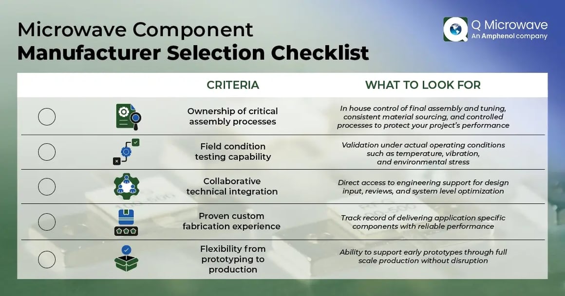
Microwave Component Manufacturer Selection Checklist
Streamline Your Microwave System Design
Working with a project that involves microwave components is a balancing act between your desired electrical performance and physical constraints. Every choice you make, from the type of filter used to the layout of the amplification stage, carries a consequence for the rest of the signal chain. You must carefully understand various relationships and trade-offs to anticipate potential bottlenecks before you move into the prototyping phase.
Instead of wrestling with discrete component mismatches and parasitic on your own, you can leverage Q Microwave's in-house technical mastery to help you build what your system requires. Reach out to our experts today to discover how you can simplify your process.
Microwave Component FAQs
Q: Why is the choice of materials more critical at microwave frequencies than at lower RF ranges?
A: Standard materials used in traditional electronics tend to absorb microwave energy and turn it into heat, which significantly weakens the signal as it travels. High-frequency designs require specialized substrates that allow electromagnetic waves to pass through with minimal loss and maintain consistent performance even as the equipment gets hot.
Q: Why do active components require more careful management than passive components in a cascaded system?
A: Active components, such as amplifiers and mixers, can introduce noise and distortion if they are pushed beyond their liner operating range. If one stage provides too much gain, it can overwhelm the following parts of the system, leading to degraded signal integrity that is difficult for the receiver to process.
Q: What is the benefit of using an Integrated Microwave Assembly (IMA) instead of connecting several individual components to create an assembly?
A: Integrated assemblies combine multiple functions into a single housing, which eliminates many of the cables and connectors that usually cause signal loss. While this makes the initial design more complex, it results in a much smaller, lighter, and more reliable system that is easier to install in tight spaces.
