

When working in complex RF environments like aerospace and defense, precision in signal control...

Summary
- Integrated microwave assemblies (IMA) combine multiple RF functions in one package. Integration can reduce interconnect complexity and address system-level requirements for signal routing, size, and packaging.
- Different integrated microwave assembly types serve different RF applications. Switched filter banks, frequency converter assemblies, transmit/receive modules, and switch matrix systems support distinct signal-processing and routing needs.
- IMA selection requires a system-level evaluation. Compare RF performance, switching behavior, interfaces, thermal and mechanical constraints, and qualification requirements against your application’s specifications.
What are the most common types of integrated microwave assemblies? What should you evaluate before selecting one configuration over another?
By definition, integrated microwave assemblies, or IMAs, are assemblies that combine functions such as filtering, switching, amplification, frequency conversion, and signal routing within a single package. Integrating these functions can help you address system-level requirements for RF performance, size, thermal management, mechanical integration, and signal routing. However, the configuration still needs to match how the assembly will perform within the larger system.
In this article, we’ll examine the most common IMA types, the factors that influence their configuration, and the key criteria you can use to evaluate which approach best fits your RF system.
Common Types of Integrated Microwave Assemblies and Their Applications
|
IMA Type |
Primary Function |
Common Applications |
Advantages |
|
Switched Filter Banks |
Combines multiple filter paths with RF switches to select defined frequency bands |
Radar, electronic warfare |
Fast selection between multiple frequency bands |
|
Frequency Converter Assemblies |
Translates signals between frequency ranges |
Radar, communications, test systems |
Integrates the stages needed for frequency translation |
|
Transmit/Receive Modules |
Combines functions across transmit and receive paths |
Radar and shared RF front ends |
Supports transmit and receive functions within a common RF assembly |
|
Switch Matrix Systems |
Routes multiple RF inputs and outputs through selectable paths |
RF test, signal distribution, radar, communications, electronic warfare |
Provides flexible signal routing between RF components |
|
Multi-Function and Custom Assemblies |
Combines several RF functions within one tailored assembly |
Systems with specialized RF, mechanical, or interface requirements |
Addresses requirements that standard architectures cannot accommodate |
Switched Filter Banks
A switched filter bank combines multiple filter paths with RF switches, letting the system select a specific frequency band without requiring a separate standalone filter assembly for each band.
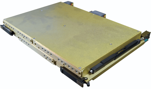
Switched filter banks are often used in radar, electronic warfare, and other systems that require fast selection between defined frequency bands while maintaining isolation between channels.
Frequency Converter Assemblies
Frequency converter assemblies combine RF components to shift signals from one frequency to another to meet a system’s frequency plan. They typically integrate mixers, local oscillators (LOs), filters, amplifiers, and related circuitry to perform upconversion, downconversion, or both.
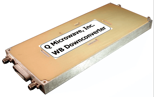
- Upconversion shifts a signal to a higher frequency, such as converting an intermediate frequency (IF) signal to an RF transmission frequency.
- Downconversion shifts a received RF signal to a lower IF, making it easier for downstream circuitry to process.
- Frequency planning and filtering can help you manage conversion products, suppress unwanted mixing signals, and control spurious responses.
Transmit/Receive Modules
Transmit/receive (T/R) modules combine RF components that manage both outgoing and incoming signals within your antenna system. Depending on your design requirements, you can integrate power amplifiers, low-noise amplifiers, switches, and phase shifters to control signal power, routing, and phase.
- Transmit signals at the required power level by amplifying outgoing RF signals before they reach the antenna.
- Receive weak signals by amplifying incoming RF signals while minimizing added noise, thereby preserving signal quality for downstream processing.
- Control signal paths by switching between transmit and receive modes and isolating sensitive receiver components from high transmit power.
You may need T/R modules for phased-array radar, satellite communications (SATCOM), or electronic warfare (EW) systems that require precise control over transmission and reception.
Switch Matrix Systems
A switch matrix connects multiple RF inputs and outputs through selectable signal paths, giving you flexible control over how signals move between your system elements. You’ll commonly find switch matrices in RF test systems, signal distribution networks, radar, communications, and electronic warfare systems where you need to route signals between multiple RF components or subsystems.
Unlike a switched filter bank, where each channel typically provides a defined filtered frequency path, a switch matrix gives you greater flexibility in selecting your signal routes.
Multi-Function and Custom Assemblies
Multi-function and custom assemblies combine several RF functions within a single integrated package. Depending on your system requirements, a custom assembly may combine filtering, switching, frequency conversion, amplification, and signal routing within one architecture.
What to Consider When Selecting an Integrated Microwave Assembly
Define your RF system requirements before comparing integrated microwave assembly configurations. Establish what the assembly must do and the conditions it must meet.
- Frequency range and bandwidth. Specify the operating frequencies, required bandwidth, and any frequency bands the assembly must support.
- RF functions and signal paths. Determine whether your system needs filtering, frequency conversion, switching, amplification, or a combination of functions.
- Electrical performance. Set targets for insertion loss, return loss, isolation, gain, noise figure, and spurious responses based on your system requirements.
- Switching and control requirements. Define switching speed, channel count, phase control, and the control interfaces your system needs.
- Physical and environmental constraints. Specify available space, package dimensions, connector types, thermal limits, and operating conditions such as temperature, vibration, and shock.
- Testing and qualification requirements. Establish the electrical tests, environmental testing, and qualification standards the assembly must meet before integration.
Once you have defined the required RF functions, the selection comes down to how those functions should be integrated into your assembly. At this stage, you are comparing viable configurations rather than determining basic requirements. Look at how each option affects your RF path, physical implementation, qualification requirements, and the performance available to the rest of your system.
Use the following criteria to compare candidate integrated microwave assembly configurations against your system requirements.
|
Selection Factor |
What to Evaluate |
What to Look For |
|
Integration Boundary |
Functions to integrate, signal-path arrangement, and external interfaces |
Fewer external interconnects where integration benefits the design, without compromising isolation, signal routing, test access, or required interfaces |
|
RF Performance Budget |
Insertion loss, return loss, isolation, gain, noise figure, rejection, power handling, and spurious responses |
Stages that consume the most performance margin, limit receiver sensitivity or output power, or contribute unwanted signals |
|
Frequency Response |
RF parameters across the full operating band, including band edges and critical frequencies |
Passband ripple, changes in group delay, reduced rejection or isolation, and other frequency-dependent behavior that approaches or exceeds specified limits |
|
Switching and Phase Behavior |
Switching time, settling time, transient response, and phase response where relevant |
Switching behavior that conflicts with system timing, phase variation that affects signal alignment, or transients that interfere with signal processing |
|
RF Interfaces |
Connectors, transmission-line transitions, impedance matching, and external interconnects |
Interfaces that contribute excess insertion loss, return-loss degradation, or inadequate isolation across the required band |
|
Packaging and Thermal Management |
Package dimensions, component placement, channel spacing, shielding, grounding, heat dissipation, and mounting |
Potential coupling between signal paths, limited thermal paths, component temperatures near rated limits, or packaging constraints that affect RF performance |
|
Qualification and Production |
Electrical acceptance tests, environmental qualification, screening, and production test access |
Requirements for additional characterization, limited access to test points, difficult inspection, or qualification constraints associated with the assembly construction |
|
System-level Integration |
End-to-end RF performance, mechanical fit, external component count, testability, and production requirements |
Configurations that meet system specifications with adequate margin and fit the available space, interfaces, qualification requirements, and production constraints |
What to Provide Your Supplier for Assembly Selection
Once you have defined your RF requirements and shortlisted suitable integrated microwave assembly configurations, the next step is to discuss your design with a supplier. Sharing your electrical specifications, mechanical constraints, operating conditions, and qualification requirements gives the supplier the information needed to assess feasible configurations and flag potential design trade-offs early.
For custom assemblies at Q Microwave, the process starts with a discussion of the application, system requirements, and design constraints. When discussing your project with our engineers, be ready to share the following details about your RF system and assembly requirements:
|
Requirement |
Information to Provide |
|
Frequency |
Operating frequency range, bandwidth, channel frequencies, and frequency-specific requirements |
|
RF Interfaces |
Connector types, transmission media, input and output configurations |
|
Electrical Performance |
Insertion loss, return loss, isolation, rejection, group delay, switching speed, and other application-specific RF requirements |
|
Power |
Input and output power, peak and average power, duty cycle, and power handling requirements |
|
Mechanical Requirements |
Available dimensions, weight constraints, connector placement, and enclosure requirements |
|
Mounting |
Mounting points, orientation, and mechanical interfaces with adjacent equipment |
|
Environmental Requirements |
Operating and storage temperatures, vibration and shock, humidity and altitude, and hermeticity or sealing requirements |
|
System-specific Constraints |
Qualification and screening requirements, material or component requirements, production quantities, test requirements, and project-specific integration constraints |
Match Your Integrated Microwave Assembly to Your System Requirements
When selecting an integrated microwave assembly, evaluate how each configuration affects your RF performance, signal routing, packaging, and qualification requirements. Choose an architecture that meets your electrical and mechanical specifications while leaving enough margin for expected operating conditions.
Use the assembly types and selection criteria in this guide to compare your options against your system requirements. Define your performance targets, interfaces, and environmental constraints early so you can discuss design trade-offs with potential suppliers and address key limitations before committing to a configuration.
If you are still determining which integrated microwave assembly configuration best fits your application, Q Microwave can help you evaluate the options and define an approach around your system requirements. Get in touch with Q Microwave to discuss your next design.
Integrated Microwave Assembly Type FAQs
Q. When should you use a custom integrated microwave assembly instead of standard components?
A. A custom assembly may be worth evaluating when standard components create difficult interconnects, packaging constraints, or integration challenges, or when your system requires a specific combination of RF functions. Compare the complete implementation, including RF performance, external connections, mechanical fit, qualification effort, and production requirements. A custom design is not automatically the better option if standard components already meet your needs.
Q. What information should you review when evaluating an integrated microwave assembly design?
A. Review the assembly’s RF test data and the conditions under which the measurements were taken. Check parameters such as insertion loss, return loss, isolation, rejection, and group delay across the required frequency range. For switched or active designs, also examine switching behavior, gain, noise figure, or power handling as applicable. Confirm that the test conditions, operating limits, and acceptance criteria match your system requirements.
Q. How Do You Make Sure That an Integrated Microwave Assembly Meets Your RF Specifications?
A. Evaluate the assembly’s measured RF performance against your system requirements across the full operating frequency range and under relevant operating conditions. Depending on the design, assess insertion loss, return loss, isolation, rejection, group delay, switching speed, and power handling. For demanding applications, evaluate temperature-dependent performance and environmental qualification results against your operating conditions and program requirements.