
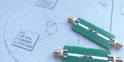
The development of microwave filter theories and practices in the 1930s laid the foundation for...
Q Microwaves’ Approach to Lowpass Filter Bandwidth Optimization

Summary
- An effective lowpass filter design must account for the system’s bandwidth and performance requirements. Narrow- and wide-bandwidth systems can require different design considerations to maintain signal quality and control unwanted frequencies.
- You can optimize your filter’s performance through material selection, design refinement, precision manufacturing, and tuning. Each stage of design refinement gives you another opportunity to improve the filter’s frequency response and meet its specifications.
- Q Microwave optimizes lowpass filters for the specific requirements of each RF system. Our engineers combine simulation, precision manufacturing, tuning, and testing to achieve the required filter performance.
___________________________________________________________________________________________________________________________________________________________
Lowpass filter design requires careful control of frequency response, particularly when bandwidth requirements leave little room for deviation. As the desired bandwidth changes, so do the design considerations needed to maintain the right balance between signal transmission and unwanted frequency rejection.
For narrowband systems, even small changes in filter design can affect the desired response. Wideband systems bring a different challenge, as they require the filter to maintain performance across a much broader range of frequencies.
In both cases, the filter needs to meet the required bandwidth while maintaining the desired signal response and performance.
So, how do you optimize a lowpass filter when the bandwidth itself changes the design challenge?
With over 25 years of experience, Q Microwave brings extensive expertise in designing and optimizing lowpass filters for demanding RF applications. Our approach accounts for the distinct requirements of narrow and wide bandwidth systems, with design strategies selected to achieve the frequency response and performance each application requires.
This article explores the considerations that influence Q Microwave’s approach to lowpass filter bandwidth optimization and how our experience informs the design of filters for different bandwidth requirements.
Optimizing Lowpass Filter Bandwidth Through Design, Tuning, and Testing
Optimizing lowpass filter bandwidth requires more than adjusting a single design parameter. Material selection, design refinement, manufacturing precision, tuning, and testing all influence the final frequency response.
Here’s how we approach each stage to optimize bandwidth while maintaining the performance and reliability your RF system requires.
1. Careful Material Selection for Optimal Performance
Filters are only as good as the quality of their parts, and optimal materials are the foundation for the best performance possible. Q Microwave uses low-loss dielectrics like PTFE, alumina ceramics, and Rogers RO4000 Series to minimize signal loss and distortion. These parts are proven to withstand challenges such as high-frequency operations and extreme environmental conditions. The Rogers RO400 series, for example, offers dielectric constants and excellent thermal stability. This makes it ideal for high-frequency applications like satellite communication and military base station antennas.
This guarantees clear transmission of signals, which is essential for complex RF systems. High-conductivity metals such as copper, silver, and gold are selected to improve signal integrity. These metals provide excellent conductivity, which reduces signal attenuation and improves overall performance.
Materials are chosen for their stable electrical characteristics across all operating temperatures. This guarantees consistent lowpass filter performance under varying conditions. By prioritizing the best materials, we enhance signal clarity and reliability, delivering superior results for RF systems. This is essential to ensure efficient communication, minimize interference, and support advanced applications.
2. Employment of Advanced Design Optimization Techniques
Advanced design optimization through adjusting various parameters is critical to achieving superior filter performance. Q Microwave utilizes sophisticated software tools for electromagnetic simulation and modeling to refine filter design. This approach is essential for several reasons:
- Accuracy and Reliability. Advanced optimization techniques ensure that RF filters meet the exacting standards required for high-performance applications. These methods allow for precise adjustments to component values, layouts, and geometries, which are critical for achieving the desired performance characteristics.
- Reduction in Development Time. By employing these advanced techniques, the development cycle for RF filters can be significantly shortened. Optimization simulates various design iterations quickly, and engineers can identify and correct potential issues early in the development process. This saves time and reduces costs associated with prototyping and testing.
- Improved Performance Metrics. Optimization techniques increase performance metrics such as signal clarity and insertion loss. By refining the design iteratively based on simulation data, engineers achieve a filter that meets and often exceeds the required specifications.
- Adaptability to Complex Requirements. Modern RF systems often operate under stringent conditions and require filters that can perform reliably across a range of environments and frequencies.
Creating and testing multiple prototypes is essential in the design process. By using performance data from each iteration, incremental adjustments can be made to refine signal clarity and other significant characteristics when it comes to narrow- and wide-bandwidth systems. This meticulous process ensures that the final design meets all specifications and performs optimally in real-world conditions.
3. Precision Manufacturing Processes
Success in manufacturing high-performance filters lies in precision. Q Microwave employs techniques such as photolithography, precision machining, and thin-film technology to achieve this. These methods enable the fabrication of components and circuit traces to exact specifications. The result is consistent, high-quality production.
Photolithography and precision machining create intricate patterns and structures required for high-frequency applications. Thin-film technology is effective for low insertion loss, high rejection, and excellent temperature stability. These attributes are vital for RF filters used in various applications, including wireless telecommunications, satellite communications, and radar systems.
Stringent quality control measures are applied throughout the manufacturing process to identify and rectify deviations that could impact performance. Thorough inspections and testing are conducted at various stages to maintain high standards of quality and reliability. This meticulous approach guarantees that every RF lowpass filter meets the desired performance criteria and delivers the best results possible for RF systems.
4. Advanced Tuning and Adjustment Techniques
Q Microwave provides expertise in every corner of every project, from component optimization to fine-tuning. The experts adjust the values and placements of individual components, such as inductors and capacitors, to fine-tune the filter's response.
This precise tuning refines the frequency response until the filter meets the desired performance criteria. Recent advancements in manufacturing technologies, such as the use of silicon micromachining and MEMS actuators, have further improved the tuning and scalability of high-performance filters.
Post-assembly adjustments, like trimming components or tweaking coupling elements, are performed to achieve optimal results within narrow- and wide-bandwidth RF systems. These fine adjustments guarantee the filter operates at peak performance, and this is how reliable and high-quality results are achieved for RF systems.
5. Comprehensive Testing and Validation
Testing leads to real results that actually deliver. Q Microwave conducts thorough testing and use cases under various conditions to evaluate the filter's performance. This includes measuring parameters such as insertion loss, return loss, and out-of-band rejection to ensure the filter meets all specifications.
Remember, comprehensive testing is crucial for identifying potential issues early and ensuring that filters operate reliably in their intended applications.
“[The] importance of testing [is] to ensure each of the components are working together to deliver the desired capability and performance when deployed in the real world.”
Performance is tested under different environmental conditions, such as temperature extremes and humidity, to ensure reliability and stability over the filter's operating range. This comprehensive testing confirms that the filter can withstand real-world conditions and maintain consistent performance. By rigorously validating every filter, we aim for reliable, high-quality results that meet the demanding needs of RF systems.
Q Microwave, Your Partner in Lowpass Filter Optimization for All Your Bandwidth Needs
Mastering the nuances of lowpass filter design is no easy feat. Every step, from selecting the best materials to employing advanced tuning techniques, culminates in filters that perform flawlessly. With over 25 years of experience, Q Microwave understands these intricacies and excels at transforming challenges into solutions.
Ready to elevate your RF systems? Trust Q Microwave for precision, reliability, and excellence in every filter. Contact us today and experience the difference.
Lowpass Filter Bandwidth Optimization FAQs
Q. What is the bandwidth of an ideal lowpass filter?
A. An ideal lowpass filter passes every frequency from 0 Hz up to its cutoff frequency and completely rejects frequencies above the cutoff. Because there is no transition region in an ideal filter, its bandwidth is equal to the cutoff frequency. For example, an ideal lowpass filter with a 10 GHz cutoff frequency would have a 10 GHz bandwidth.
Q. What is the best setting for a lowpass filter?
A. The best lowpass filter setting is the cutoff frequency that provides the required balance between signal transmission and unwanted-frequency rejection. You should set the cutoff above the highest frequency your system needs to pass, while keeping it low enough to attenuate unwanted signals beyond the required operating range. The filter's insertion loss, rejection requirements, transition band, and application environment should also factor into the final setting.
Q. What is the recommended frequency for a lowpass filter?
A. We recommend selecting a cutoff frequency slightly above the highest frequency your system needs to pass. This should provide you enough room for the filter to maintain the desired signal while achieving the required attenuation beyond the passband. The exact frequency should also account for the filter's transition band and the performance requirements of your application.